Ergodox Aleph Build Log Chapter 5: In Which It's Fine
crossposted from cohost
I picked QMK because there was already code for the Ergodox Infinity. There were also already code for the class of LED Drivers I'd chosen for my RGB backlighting. Surely it would just be a matter of combining those two things together!
Programming
There are many things that make Arduino popular and easy to use. But the most important thing is the ecosystem: You write their language (mostly C) in their editor, and you can easily program their board over USB. No extra tooling required, and the community has libraries to do almost anything you could want.
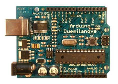
The part that makes that USB magic work is called the Bootloader, and just about every board has one. Under certain conditions (usually immediately after a reset), the board will enter “programming mode.” It has enough code to boot up the USB driver and listen for a certain set of commands from the computer. When it receives a binary, it overwrites a region of the chip's built-in flash memory with the provided machine code. Importantly, you can't command a bootloader to overwrite itself, thus preventing people from turning the board into an ineffective paperweight.
But the bootloader is just code, there's nothing magic about the chip. How do you get the code on there the first time? You use a programmer.

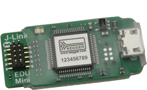
The original Ergodox Infinity has contacts on it for a Needle Adapter. These make sense for a “mass” production run. But the cables are very expensive for a one-off like mine, so I replaced it with a standard 2x5 SWD header. A ribbon cable connects to the end of the programmer.
In addition to flashing a binary, you can use a programmer as a debugger, stepping through line by line using GDB.
This will be important later.
QMK
QMK is a very popular firmware for mechanical keyboards. There are a lot of keyboards in the repository, including some very small-run boards. The online configurator simplifies customising the functionality of your keyboard, the bread-and-butter of mechanical keyboards. The internal API supports a large number of features including RGB matrices and LCD displays, and before I built my keyboard I made sure everything was in the supported list. I expected to simply modify the existing Ergodox Infinity firmware files for my own keyboard, and initially that's what I did. But as last entry's cliffhanger mentioned: It didn't work. Time to debug.
The Internals
Firmware like QMK doesn't have an “operating system” in the way you might normally think. There's no Linux kernel churning away, usually no kernel mode/user mode difference at all. But there are some very operating system-like components that it does have.
One is the Hardware Abstraction Layer, or HAL. This is a lot of what modern operating systems do: your computer doesn't care if your keyboard is USB, Bluetooth, or PS2 once you've got it connected. The parts that care about that connectivity are insulated from the parts that care what key you're pressing. Likewise, you don't want to have to rewrite your display control code from device to device just because they picked different pins on the microcontroller. The HAL provides a way to write a driver just once and use it accordingly.
We also need a real-time operating system, or RTOS. A normal OS like Linux generally just tries to make sure every task (browser, shell, backup daemon, Magical Diary: Horse Hall) is run as much as it needs. But sometimes you need better guarantees than that. For a keyboard, you absolutely need to scan the key matrix every so often. Otherwise you don't have a keyboard, you have a fun stim toy that lights up. An RTOS handles constraints like “This must run every 500 milliseconds” and “this task is always more important than others.”
QMK uses a project called ChibiOS, “a complete development environment for embedded applications.” I have learned a lot about this, because I spent a lot of time digging through QMK firmware.
Things I Tried Which Didn't Work
Serial Debugging
There are lots of ways to “debug” an application when something is going wrong.
One of the most straightforward ways is “print” debugging, where you add a bunch of “here I am!” “this worked!” “no problems here :)” statements to your application.
Unfortunately this application doesn't have a screen I can use, so I can't just stare at a console the way I usually can. (Yes technically it does have a screen. But it wasn't working yet, and anyway it could only show a few characters.
Fortunately there's a solution to this: Serial debugging! That's right, that protocol that hasn't really changed since the seventies is the hero we need.
Now we just need to connect the spare serial line and…
Ah.
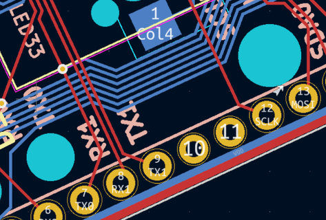
Oh well. There are two other serial lines, designed for connecting to the other half of the board. I don't have one of those, I can just use the lines that talk to that. A few changes in the QMK configuration and we're good to go.
Now usually these would be connected to your computer through a USB-to-serial adapter. I don't have one of those, but I do have a Raspberry PI…
PyCon 2013
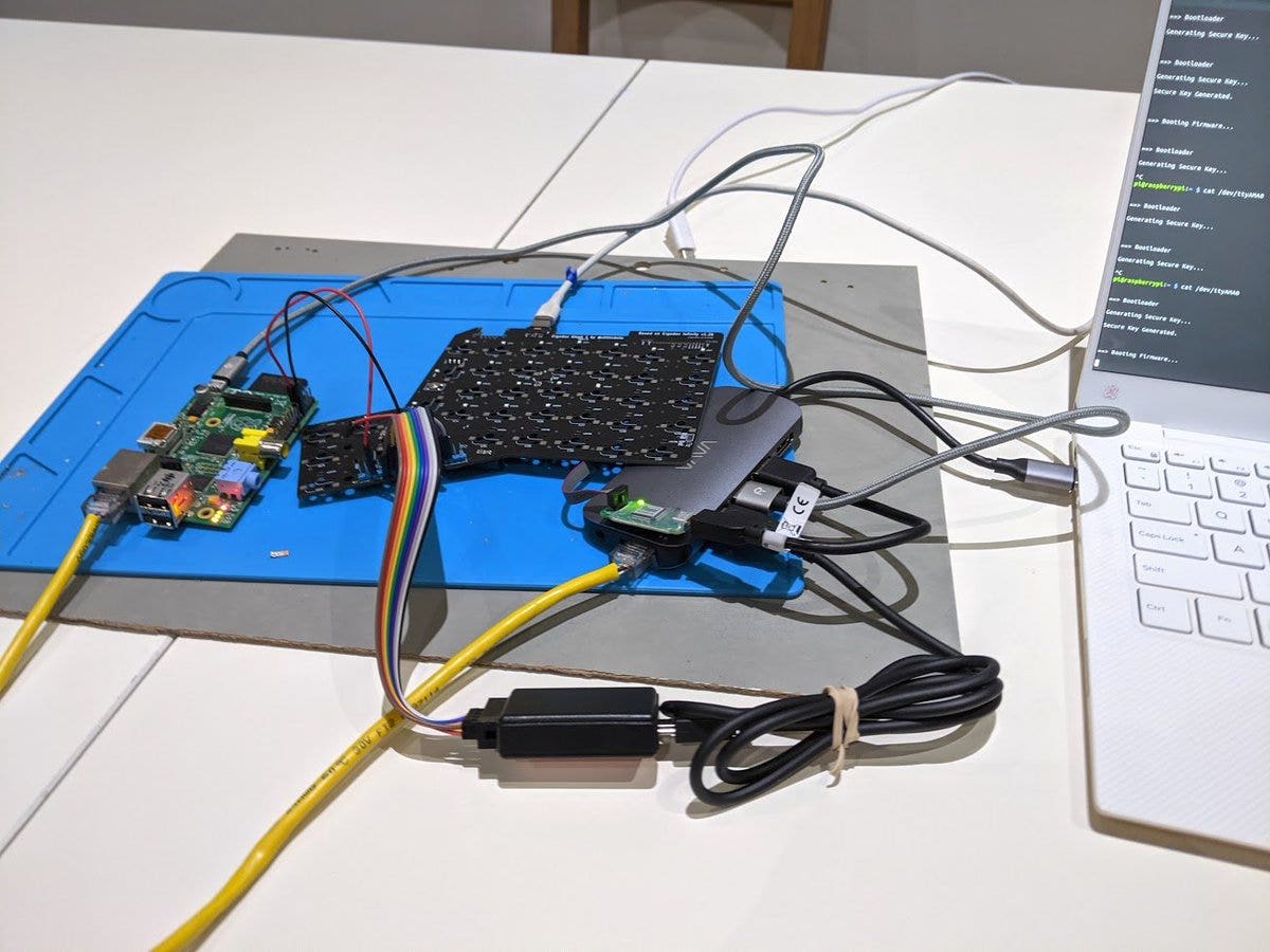
Unfortunately, after all of that work, the logs didn't tell me anything particularly interesting. The instructions I thought were executing did seem to be, and when they weren't the printf bisect search wasn't particularly forthcoming.
Resoldering Chips
Of the two chips, the LED driver is a QFN-40. That means it's a Quad-sided Flat package with No leads. Of particular note, it's very difficult to tell if solder joints are actually… soldered, since they're entirely out of view. The solder pads are clearly visible, but the actual connections to the chip are less obvious.
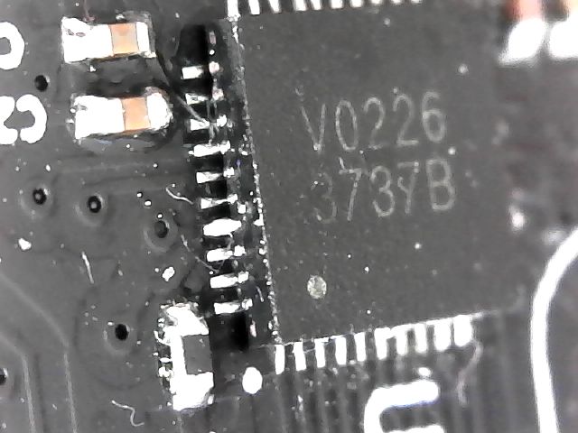
An improper connection could result in outright failure, but that's the best case scenario. It could also result in weird, inconsistent behaviour or fry a chip altogether.
The easy part is removing a chip. The same hot-air reflow station that melted our solder paste the first time can melt it again (or “reflow” it). Once all the solder on the pads is liquid, the solder can be soaked up with a wick or the chip simply removed entirely. Be careful and quick though! Chips are only really designed for one high-temperature soldering session, and further sessions could damage them.
Unfortunately, while the first soldering job can make use of our fancy stainless steel solder mask, subsequent soldering can't. The mask wants to cover the entire board, but now most of the board is covered in components and the mask can't sit flat.
Complicated SMD components that repair shops might want to replace actually have stand-alone stencils available. But even if they did exist for little QFN-40 chips, there's too many components nearby to use one.
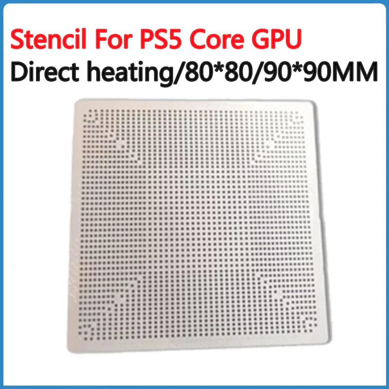
This means, instead of nice aligned strips of solder paste, I have to kind of improvise with a combination of a toothpick, tweezers, a USB microscope, and hope. And of course, flooding pads with too much improperly placed solder paste makes bridging even more likely. As with many things embedded development, the solution is to simply not make any mistakes.
Assembling a Second Board
I originally bought enough components for at least two boards, more if they didn't get all their connectors and accoutrements. Using what I learned from my first attempt at assembly, I performed the exact same actions and expected different results.
I did not get different results.
Test Points
I neglected to break out test points for any of the LEDs, so I manually soldered wires to a few places where LEDs would theoretically go.
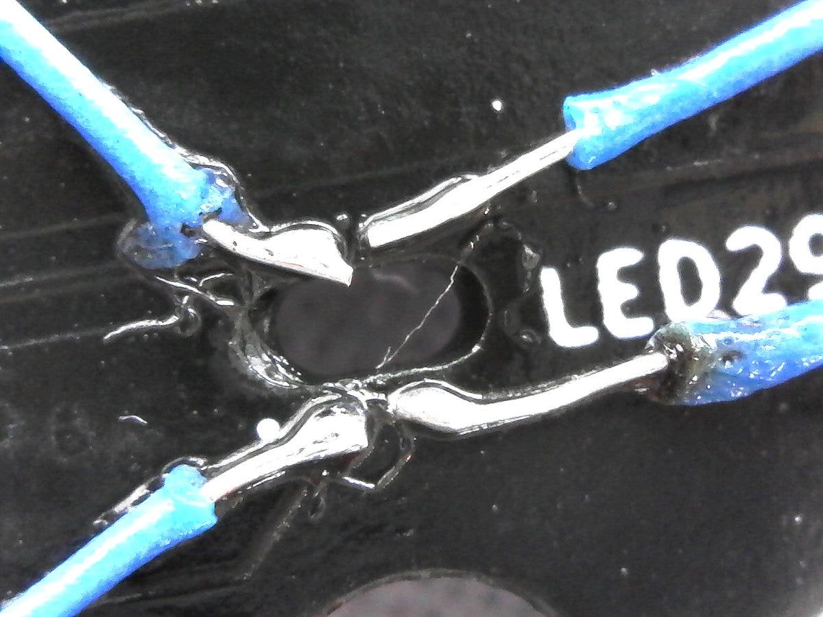
My initial thought was to test these with a multimeter. Unfortunately they all use PWM, so even when “working” the voltage is going to be zero most of the time. What I really would've needed to check this was an oscilloscope, which I don't have.
Step-through Debugging
“Debugging” is a general process, but there's a specific kind of program called a debugger. Generally, it allows you to pause and step through execution by instruction, set breakpoints, and examine variables.
ARM chips have an interface called SWD, or Single Wire Debug to allow this kind of interaction. It, naturally, requires at least two wires. Those are the pins the programmer uses to flash programs, and now we can use it to plumb the depths of this microcontroller.
The debugger I was taught to use originally was `gdb`, a command-line application that's older than I am. And in typical computer fashion, that's actually still what I use.
A tool called OpenOCD (no relation to the disorder) uses the programmer, but of course it's not plug-and-play. First, you have to run a command that flashes OpenOCD onto the programmer itself. That command will start up an in-between program that runs on your real computer, and exposes a telnet port that gdb can connect to.
And of course, since the NXP chip is Arm, you need a special multi-arch version of gdb.
I also eventually got this working in shudder Eclipse.

From there, I had to figure out the bootloader written for the original Ergodox Infinity. And a bunch of weird messages about code optimization.
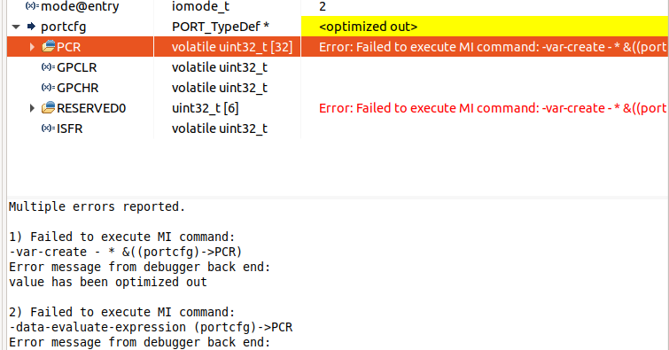
And in the end, I didn't really learn anything new. Well, I learned how to use a debugger on an ARM chip. But the code I thought was executing was, and I was no closer to a solution.
Disabling EzPort
The chip I was using had an “EzPort,” a sort of proprietary SWD equivalent. At one point a random forum post suggested that this mode could be inadvertently activated, which would prevent any normal functioning from occurring. There was a way to disable this in software, but of course that's not useful if you can't get it to boot.
Luckily, there was a pin I could pull down to disable EzPort altogether. Unfortunately I hadn't broken it out, so I had to do a really fiddly soldering job:
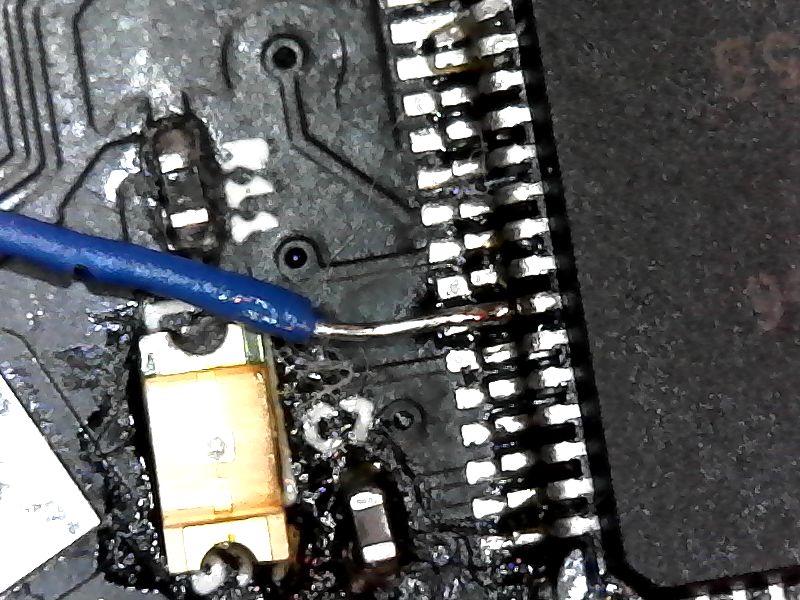
This did not make a difference.
Teensy
At a certain point I stopped being able to communicate with the microcontroller on the board altogether. In an attempt to eliminate as many variables as possible, I bought a Teensy, which has the exact same chip as the board I was using.
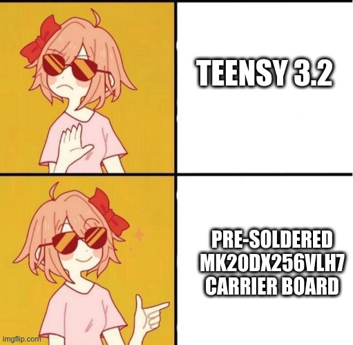
Unfortunately I wanted to do step-through debugging, and the Teensy doesn't break out those pins. So I did a bunch of soldering nonsense:
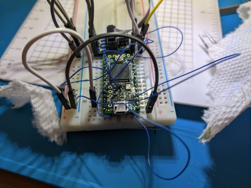
And I wired up the I2C, hoping to see different results. But for whatever reason this never really worked. Perhaps my soldering skills were inadequate, or I damaged a chip, or I just misunderstood what I was doing. Regardless, this was ineffective.
And of course, all of this didn't work. Next time, I'll talk about something that didn't work but I put so much work I gave it its own chapter: I²C.