Ergodox Aleph Build Log Chapter 3: Case Studies
crossposted from cohost
Most keyboards have a case of some kind. Electronics are fragile, and the last thing you want is to short important pins or tear a tiny resistor off the bottom. Even minimal “bare circuit”-vibe keyboards tend to use at least a bottom case:
Now, this leads to a bit of a problem for me. There are plenty of existing 3D printable cases for the original Ergodox. It's a very common form factor, and it has a commensurate amount of support.
However, because my design was based on the Ergodox Infinity, these wouldn't work. The cables would be on the wrong side, in the wrong form factor, and there'd be no hole for the LEDs. Perhaps an existing one could be modified by someone more skilled, but not by me.
The Ergodox Infinity, too, has open-source case designs, but these aren't 3D-printable. Instead, they're made of laser-cut acrylic. At least at the time I was working on this I didn't have easy access to a laser cutter. But even if I did, there was another problem: My keyboard wasn't quite the same size.
I did my very best to keep the dimensions exactly the same as the original Infinity. Unfortunately, my addition of stabilisers and Kailh hotswap sockets meant one of the edges was just a little too small. I brought it out, probably less than a centimetre, but the damage was done. I couldn't use an off-the-shelf case. Obviously, then, I had to design my own from scratch.
Selecting a CAD Program
Unlike EDAs, all of the most popular CAD programs (Solidworks, Fusion 360, 3DS Max) are proprietary. But there is a very popular 3D modelling program: Blender. Surely those are basically the same thing, right?
They are not! Ask me how I know. CAD is designed with a strong focus on real-world dimensions, on adjustable parameters, and a bunch of tooling and views that make it better suited. It turns out trying to do CAD in blender is a bit like trying to edit a PDF in Photoshop: technically possible, but far from ideal.
There are a couple of free-as-in-freedom CAD suites available. The first one I encountered was OpenSCAD, which I'd used to build 3d-printable keycaps.
After a bit of time messing around with it, I realised this was a very different kind of program from the Autodesks of the world. Instead of clicking, dragging, and scrolling, objects were built entirely up in a custom scripting language based on tunable parameters. This works great for things that you'll constantly want to tweak, like keycaps. But for my design, which would only ever really need to be one size, that wasn't particularly helpful.
Also, the learning curve seemed steep even by 3D modelling standards.
Instead, I settled on FreeCAD. This had a much more traditional user interface: you can make squares, extrude them, carve them out, the works. Armed with documentation and the knowledge that 3D modelling is notoriously complicated and difficult, I set off to build my 3d-printable custom case.
How hard could it be?
KiCad 3D Models
The best way to ensure that my case design lined up with my PCB, especially when I didn't have said PCB in hand yet, was to work based on the same plans. Fortunately, that was doable! There's a set of scripts called StepUp that focus on integrating KiCad designs into Freecad shapes.
To do this, though, first KiCad needs to actually know what the board will look like. It understands the geometry of the board itself, as we've already seen, but there's a lot more that will need to fit into the case than just the PCB.
The basic way KiCad works is by matching up IDs with symbols on the schematic side and footprints on the layout side. The first resistor you lay down will be R1, Capacitor C1, microcontroller U1, voltage regulator Q1 (in order of most to least comprehensible) and so on.
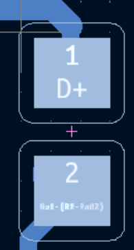
On the schematic side, you might say you want a 33Ω resistor, which would render as a box
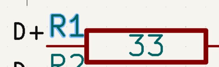
You also pick a footprint there. There any number of different sizes of resistor that could meet the 33Ω mark, from the classical cylinder to nearly microscopic. In this case, we've chosen a 1005 metric / 0402 imperial, which means 1.0mm by 0.5mm or 0.039” by 0.020”. When we sync our changes to the schematic, the program will look for R1, make sure it has the right Value (33Ω) and Footprint (1005). From there, it will render the footprint of the pads to be soldered to.
While you're doing this, you can optionally specify a 3D model. This allows KiCad to render not just the pads, but the entire component as well.
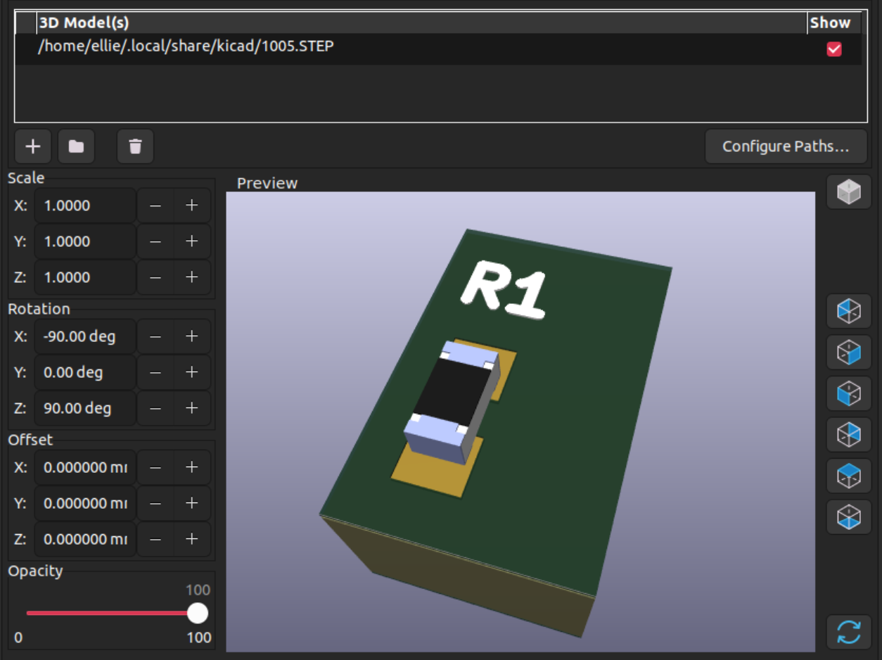
Unfortunately, this is largely a manual process. For a common size like 1005 it'll be easy to find a component, but something like a keyswitch or an LED might require scrounging around SnapEDA, Mouser/Digikey, and other places to find a footprint that matches. You need to be a little clever, too. Nobody will have a models for a NXP MK20DX256VLH7, but there's plenty of LQFP64 models because many chips use the same form factor.
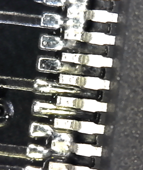
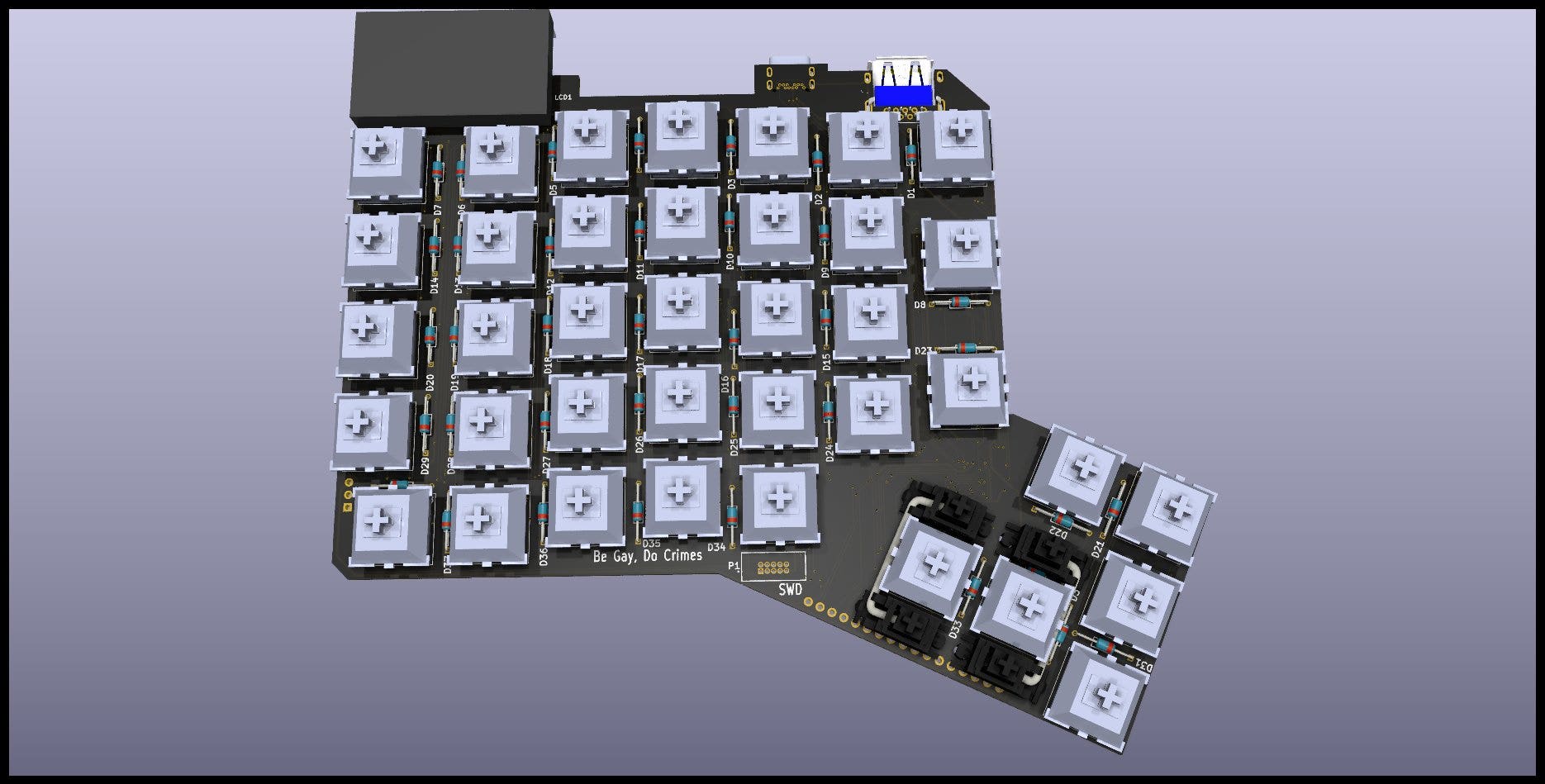
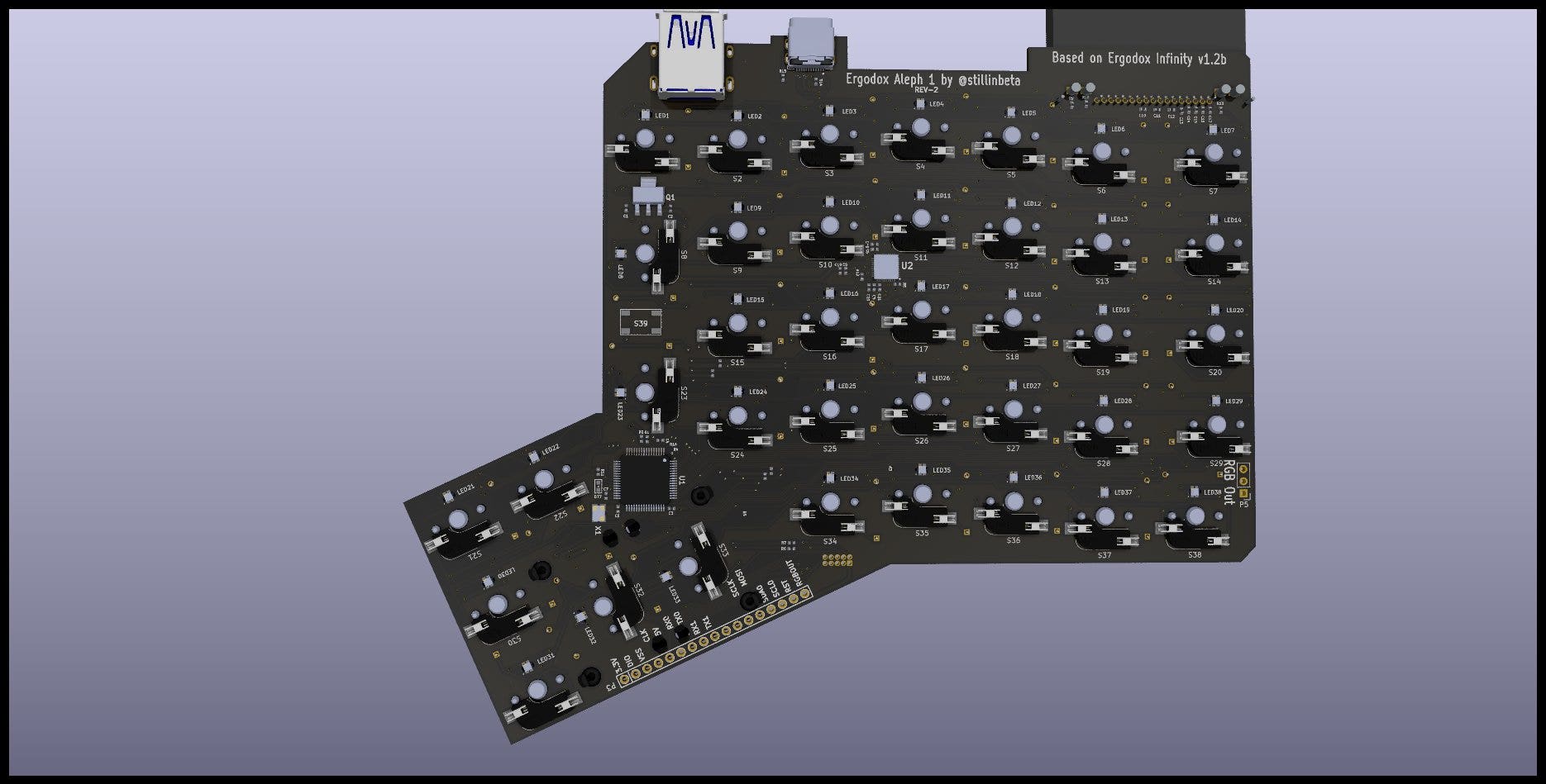
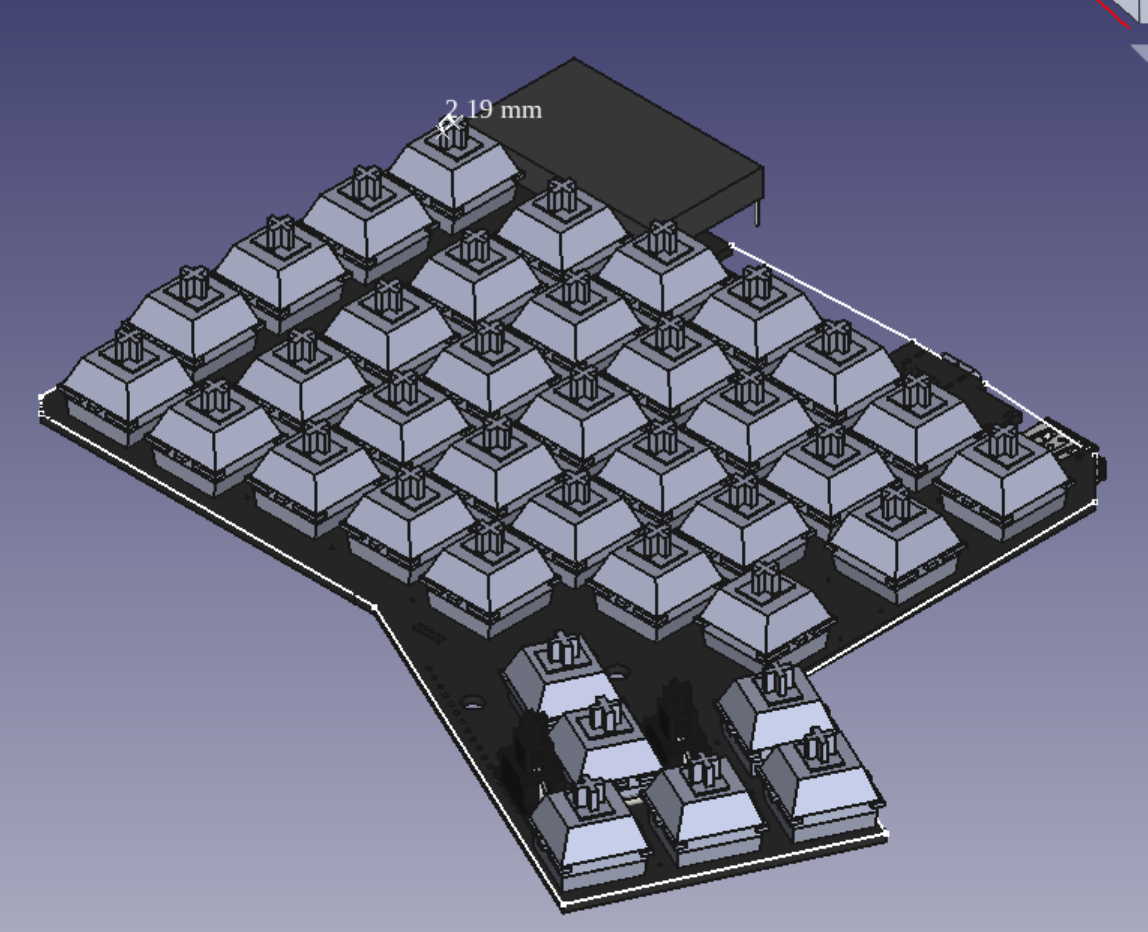
After a lot of painstaking work, you can render a fully populated 3D model of your board for beauty shots.
StepUp
This is, once again, not a tutorial, because I don't actually know what I'm doing. Go find a real guide if you need help!
The basic process for StepUp is that you import a PCB, it produces a bunch of error messages, you spend a bunch of time staring at them, futzing with settings, and tearing your hair out. If by divine providence you manage to get it all imported, you'll be left with a 3D model that badly lags your computer.
Oh at this point I realised I probably should use a beefier computer than my several-year-old ultrabook. But I pressed on.
CAD modelling is all about precision. You don't want to just eyeball your keyboard grid, you want to measure it. So at this point I “projected” the schematic onto a plane.
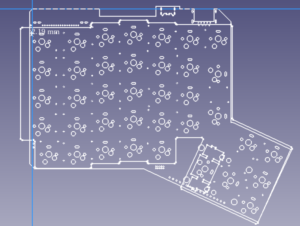
Then you can convert that sketch into guidelines, and you can draw based on them.
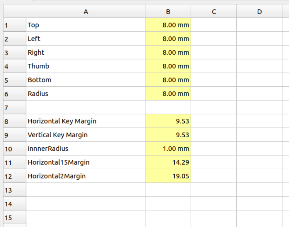
FreeCad is a “parametric” cad program, which means you can set tunable parameters. Here's some of mine from an earlier draft:
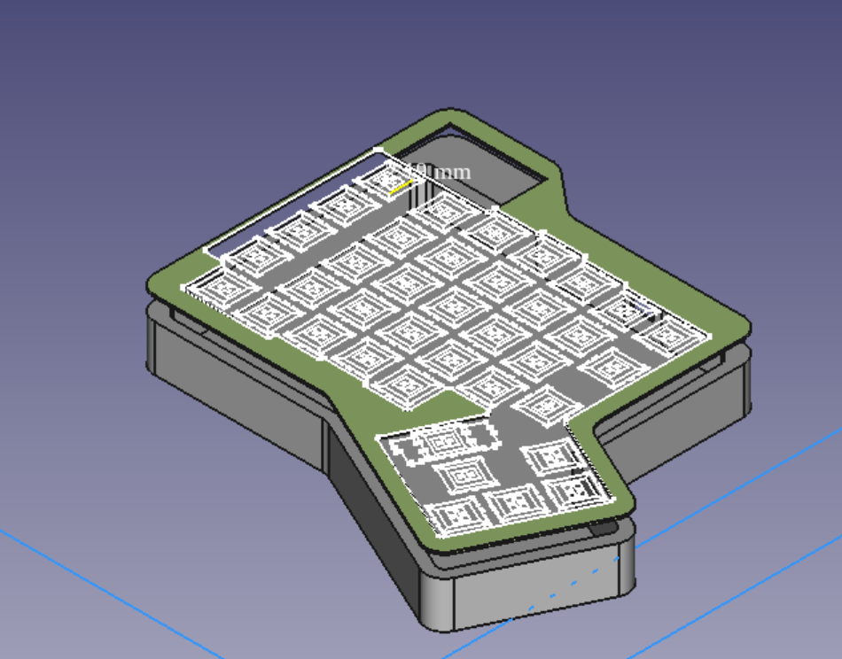
 You build up operations like “draw lines that are always
[HorizontalKeyMargin away from the outer edge of keys],” and slowly
build them up, extruding surfaces and cutting holes.
You build up operations like “draw lines that are always
[HorizontalKeyMargin away from the outer edge of keys],” and slowly
build them up, extruding surfaces and cutting holes.
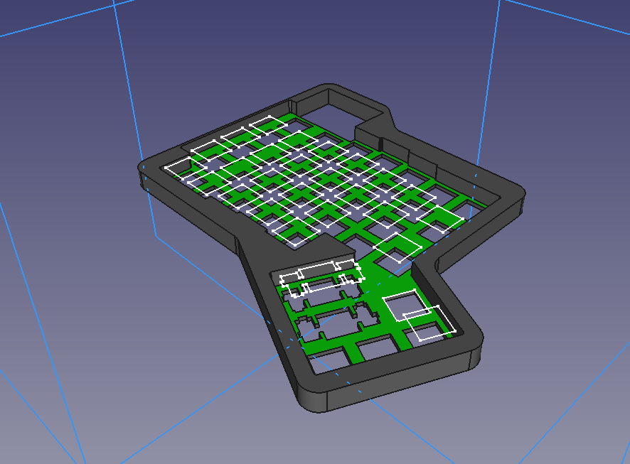
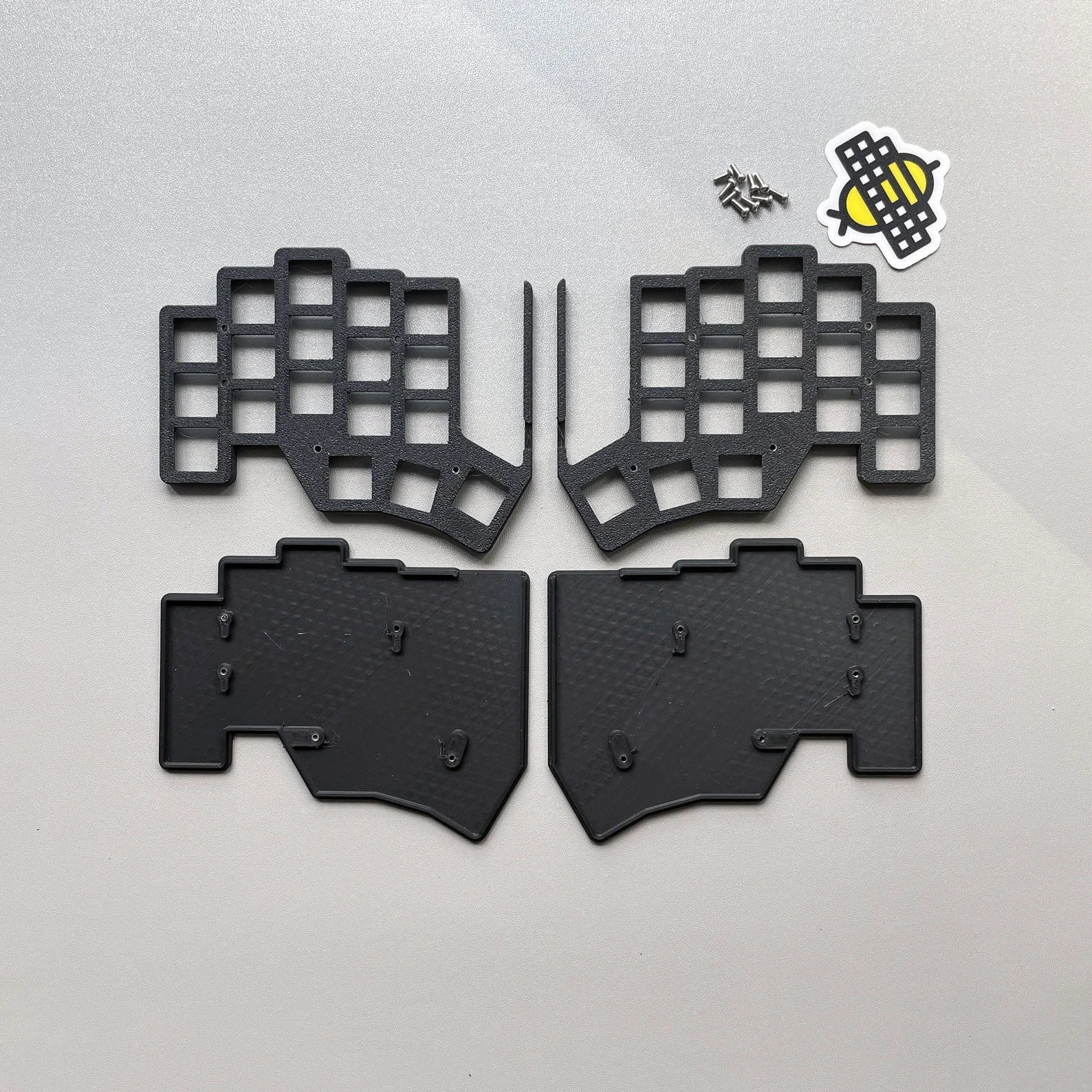
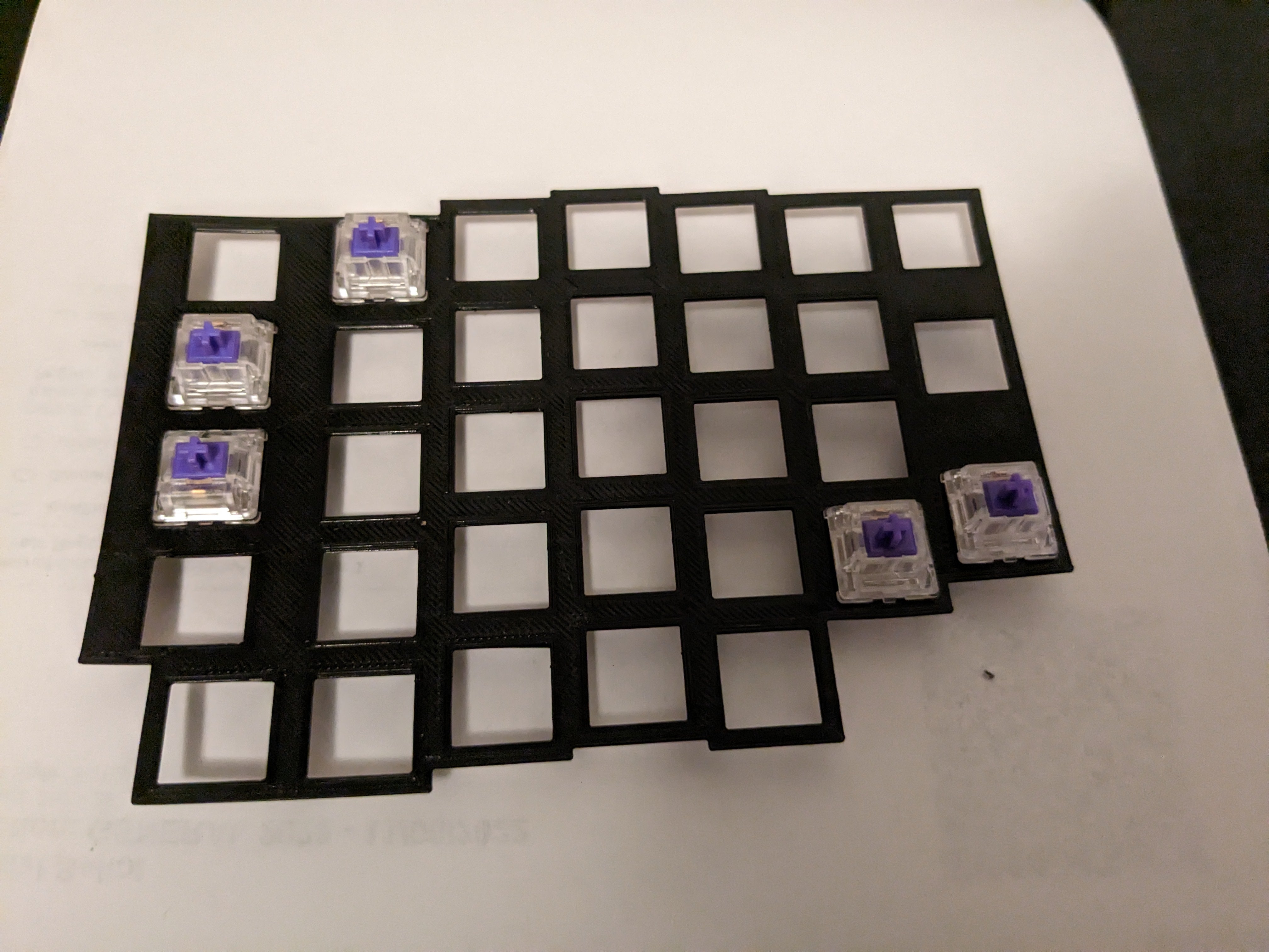
I even printed out some prototypes of the key stabiliser plate:
But I still haven't really finished. Because pretty soon, I got a fedex package from Shenzhen.
Next time on Aleph Build Log: How Hard Can Soldering Be